The Lowspec project
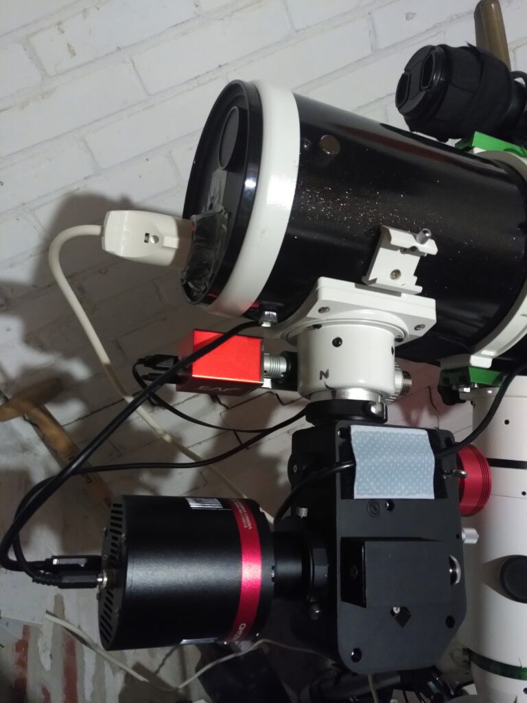
The Lowspec DIY spectroscope was designed by Paul Gerlach and placed on Thingiverse.com. The project is made around the idea to create a slit spectroscope on a budget. Commercially available slit spectroscopes with the same range of resolution as the Lowpec 3.0 generally cost in exces of € 3.000,- ranging up to € 6.000,-. By building your own spectroscope from of the shelf optical parts and a 3D printed body and parts, spectroscopy becomes accessible to more amateurs with an interest in spectroscopy. In total for my building project I spend about € 800,- (in 2022). All the optical parts and the micrometer cost about € 600,-. The ASA plastic fibre to print it all cost € 30,- and I spent about € 50,- on the needed screws, bolts, nuts, springs and so one. My brother allready had a 3D printer, and the neccesary experience using it (Thanks little Bro! 😉 ). A further € 90 was spent on a 2 inch rotator to connect the main camera to the spectroscope with the ability to rotate it freely. This is very handy as the spectral image needs to be perpendicular to the image frame of the camera.
This does not account for the guide camera I bought second hand. You could use a guide camera you allready own and use for deep sky imaging and attach that to the spectroscope when needed. But I found it convenient to have a guide camera dedicated to the spectroscope. In this way I can still use the normal guide scope and camera in parallel for polar alignment and also for plate solving to make it easer finding the target to do spectroscopy on. This is handy as the field of view of the guide camera on the spectroscope will be small.
I have made the 3.0 version of the Lowspec spectroscope. The object files which need to be printed can be found on Thingiverse, along with an elaborate building manual:
https://www.thingiverse.com/thing:2455390
For anyone interested in building one themselfs I have collected the learning points of my building proces here on this page.
The lowspec 3.0 design
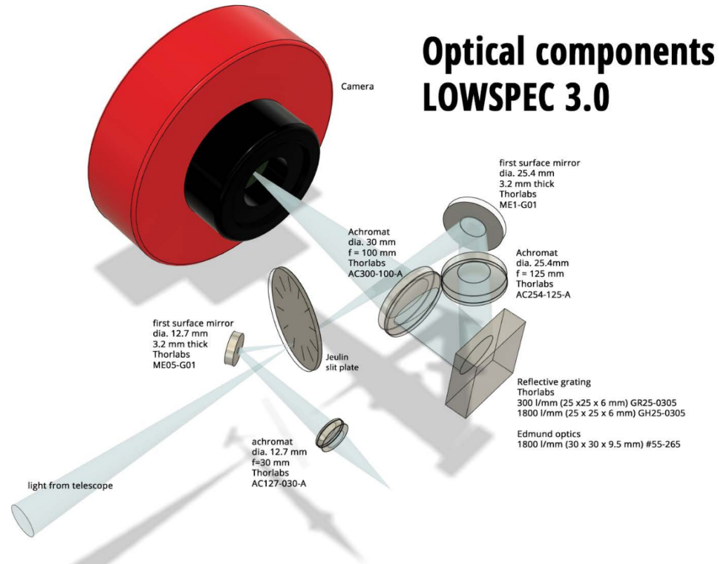
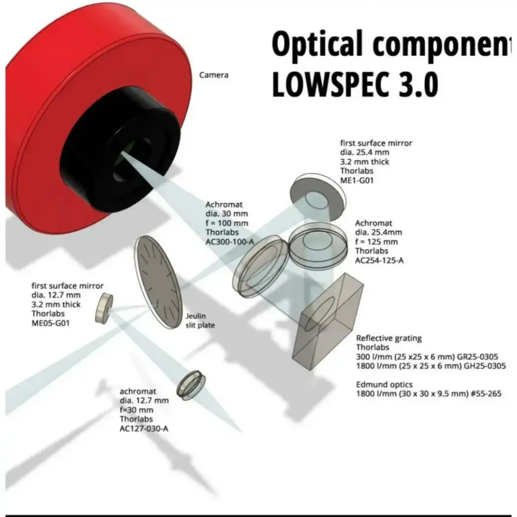
The lowspec spectroscope is build as a slit spectroscope. In this design all the commercially available optical parts are placed in a housing which needs to be 3D printed. The diagram below shows the optical parts in the design and the light path. Light enters from the left, comming out of the telescope.
The slit plate
The big difference from the staranalyzer grating I have been using earlier for spectroscopy is the slit plate. The function of the slit is to select a thin slice of light from the optical path and let it through to the working part of the spectroscope. The advantage of this slit is that the resolution of a spectrum of a star is no longer dependent on seeing (or bad focus). In principle a thinner slit will produce higher spectral resolution. Of course at the cost of less light with a thinner slit. The neat thing of the Lowspec 3.0 design is that it incoporates a slit disk with 12 slit widths; from 10 micron up to 200 microns. In practice I use the 10 and 20 micron slits, depending on the magnitude of the target star.
The slit plate can be bought from the French company Jeulin. Take care though that you get the single slit disk, as Jeulin also sells the same disk with 12 double slits.
https://jeulin.com/jeulin_en/204139.html
The width of the slit can be easily changed by turning the dial on top of the body. It snaps in place using a spring and ball bearing. So there is no worry that it will be misaligned.
At the slit 2 things happen.
- Spectroscopy module: The light passing through the slit encounters; a mirror, a collimator lens, the dispersion grating and finally the camera lens. The main camera needs to be placed at the focal point of the camera lens. On this camera the spectrum is projected. Therefor it is also sometimes called the science camera.
- Guiding module: This is neccesary to be able to see the starfield of choice and place the target star on the slit. The view from this guide camera is used in PHD2 or another guiding program to keep the star on the slit for long exposures. Without this module there is no hope of getting a star on the slit. Or when you have a star on the main camera, you can’t make sure in any way that you have the right star.
An other big convenience of a slit spectroscope over a slitless one such as the star analyzer is that you can take spectra of objects that are not point sources like stars. Extended objects, such as nebulae, galaxies, the day or night time sky, or any lamp you have in and around the house can be made a spectrum of as the slit makes the source in to a point source (or line source).
The guiding module
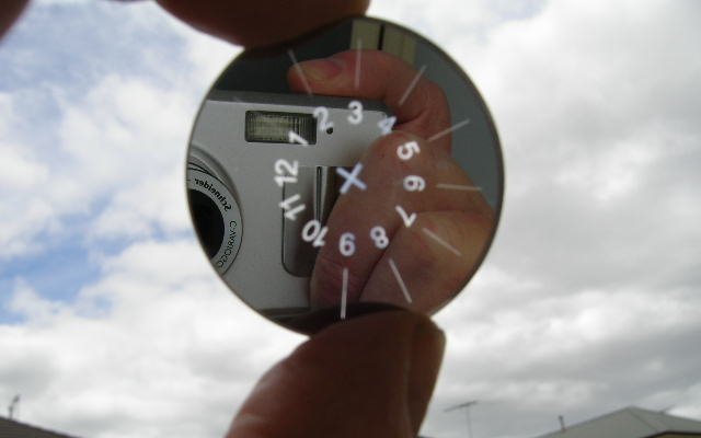
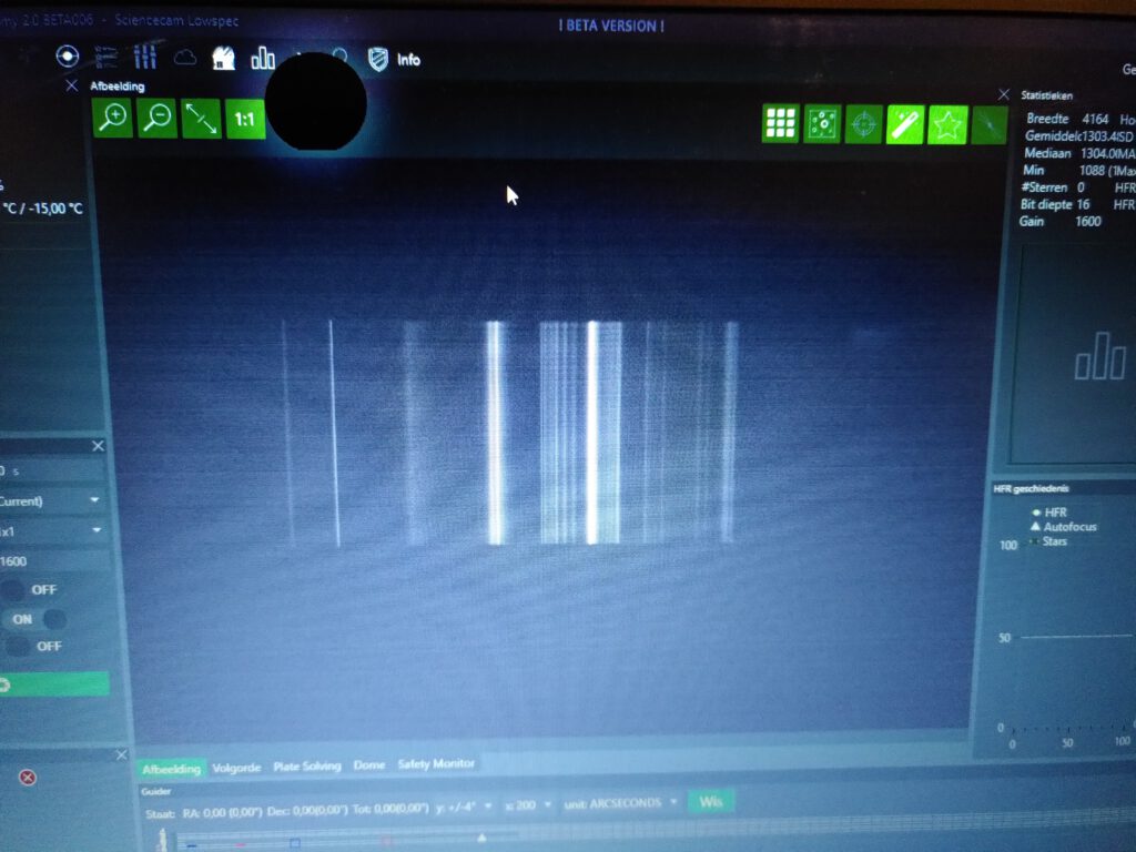
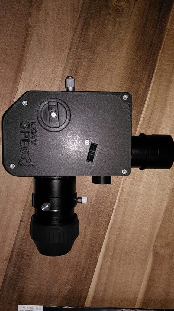
The light that does not go through the slit, reflects of to another pick off mirror and out of the guide camera end. At this end the guide camera is placed. The design does not have an intracate focussing mechanism for the guide camera. To focus slide the guide camera back and forth in the printed 1,25″ housing untill the image of the slit is as sharp as possible and lock it with the lock screw. To focus this guide camera, place a bright lamp in front of the telescope end of the spectroscope and that will create an evenly illuminated plane on the sensor, with one black stripe created by the missing light that went through the slit. Once focused, you don’t touch this focus mecahnism again. To get a starfield in focus under the night sky you will use the focussing mechanism of the telescope, NOT the focus of the guide camera.
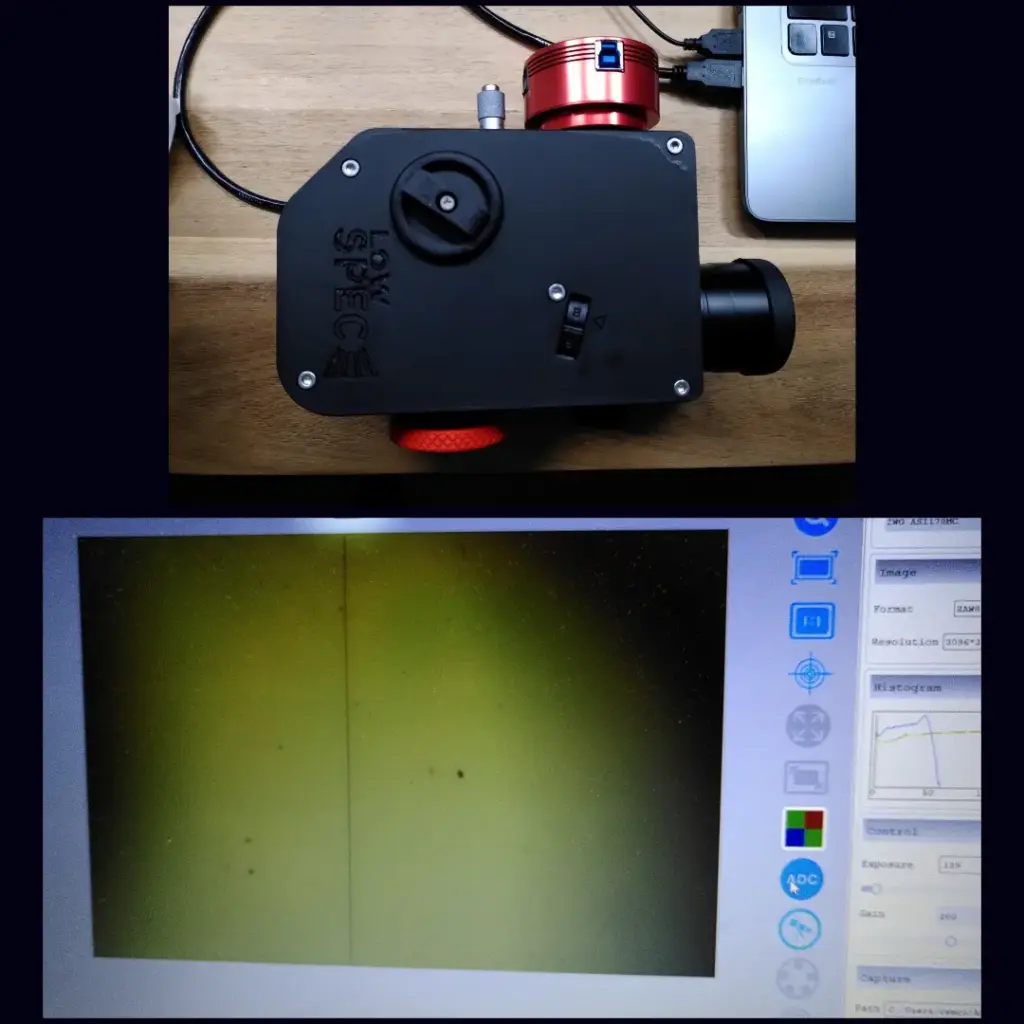
(bottom) the view of the guide camera in focus on the slit using a lamp in front of the telescope end.
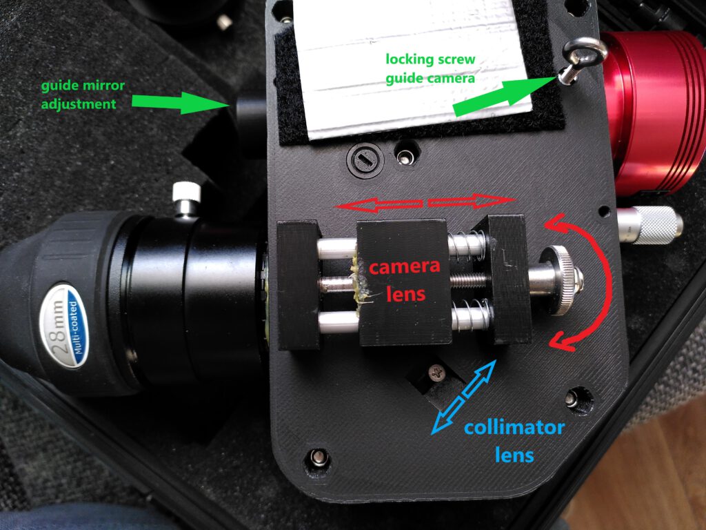
The spectroscopy module
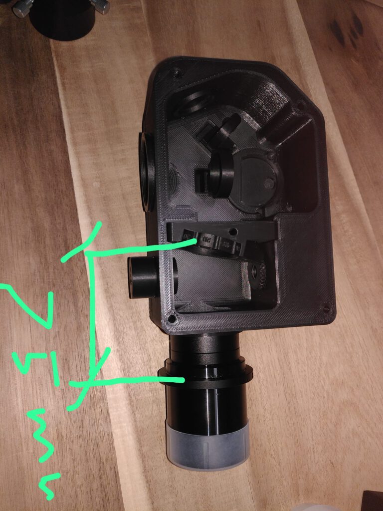
The image below shows the printed housing with lens holders, but without the lenses. Left of the partition is the spectroscopy module. The light comes in from the right, through the slitplate at the partition. After that it encounters a flat mirror at the far left which bounces it to a collimator lens. After the collimator lens comes the diffraction grating. The grating holder is placed on a turn table. The turn table enables a fine adjustment of the grating angle, through a micrometer on the outside. In this way you can choose the part of the spectrum which lands on the main camera.
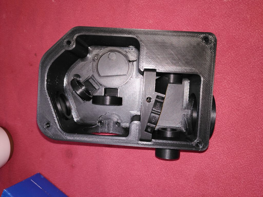
The last element is the camera lens. This lens focuses the parallel light beams on to the main camera sensor.
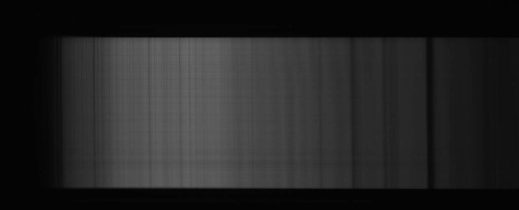
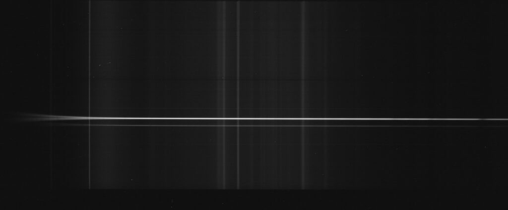
When finished, the image that comes out of the spectroscopy module onto the main camera shows a spectrum.
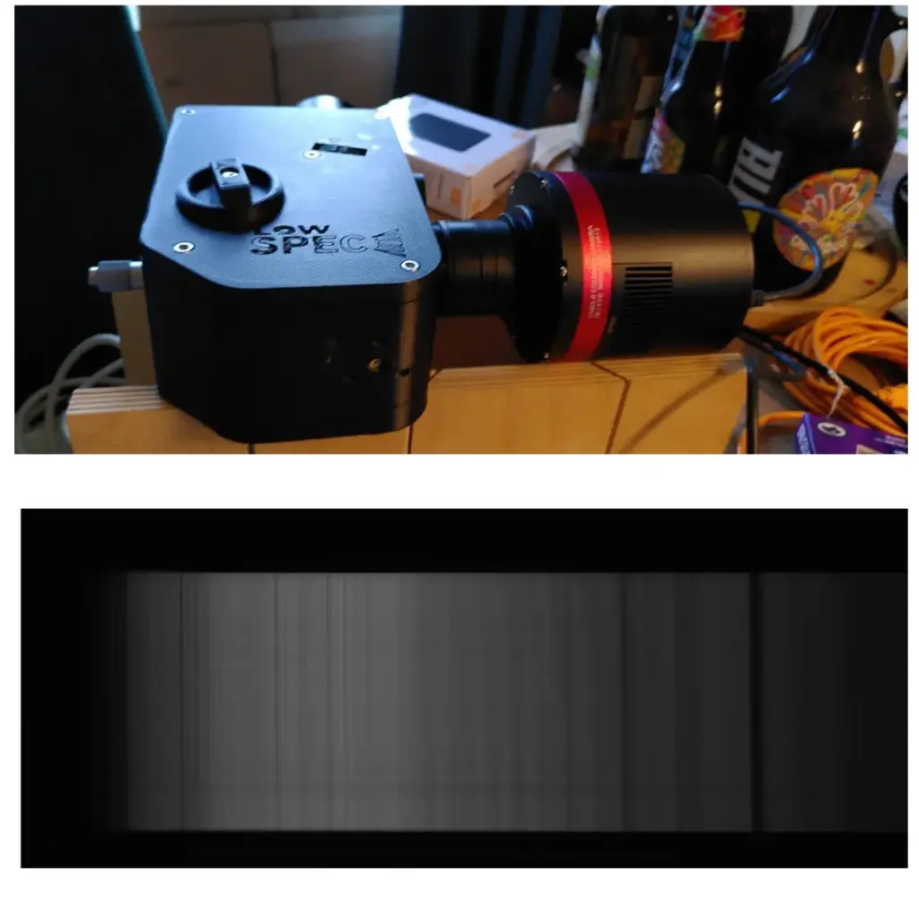
(bottom) spectrum on the main camera, in this case a spectrum of the daytime sky showing the Fraunhofer absorption lines from sunlight.
wavelength selection
At my resolution of R =1400, with the 300 lines/mm I can get the whole visible range (3800 to 8000 angstrom) within the image frame of the camera. However, when you use a higher resolution grating with more lines/mm only a smaller part of the spectrum will fall on the sensor. To alter the range of the spectrum that falls on the sensor, the Lowspec is designed with a turntable under the grating to alter the grating angle. It is changed by turning the micrometer and it is quite precise. The video below shows this proces. Attached is a DSLR and a neon calibration lamp at the telescope end.
Changing grating for different resolution
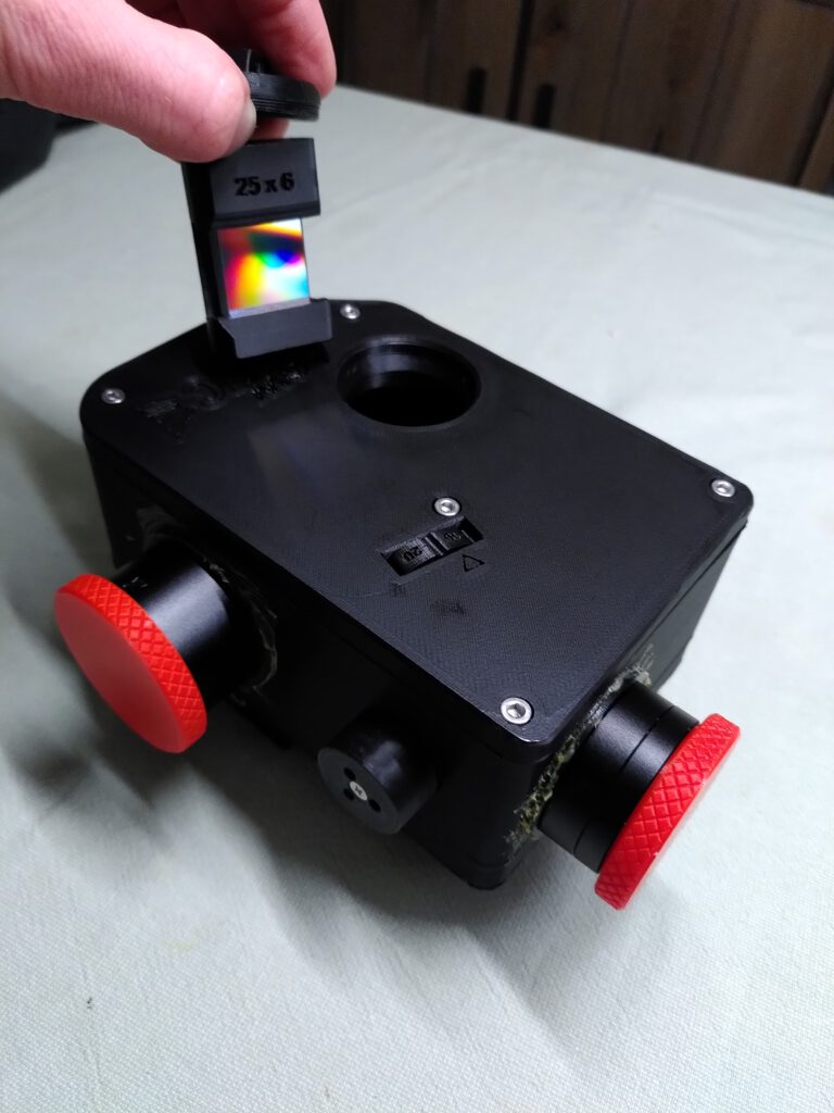
The Lowspec 3.0 design comes with a neat feature where you can easily swap out the grating for a grating with different number of lines/mm, so a different resolution. The video below shows me inserting the grating into the body.
Alignment and focussing
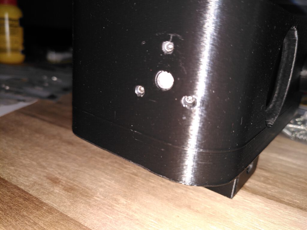
The alignment of the 2 mirrors in the system is done with a 3-point adjustment with hex bolts and a center bolt to adjust the distance. This works very easy and intuitive, and is done as you look at the image on the camera sensors.
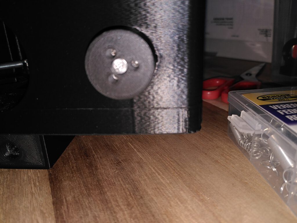
Focus of the collimator lens and mirror alignment
Focussing the collimator lens is done with a simple philips screw. This focussing has to be done once at collimation of the spectroscope. This is not very easyily adjustable but it has to be done only once.
The simplest way to get the collimator lens in the right place is by doing this without the camera lens in place. I did this by placing a 15×70 binocular in front of the main camera opening and a LED light in front of the telescope end. (see image below). You could also do this with a (guide) scope with a eye piece attached.
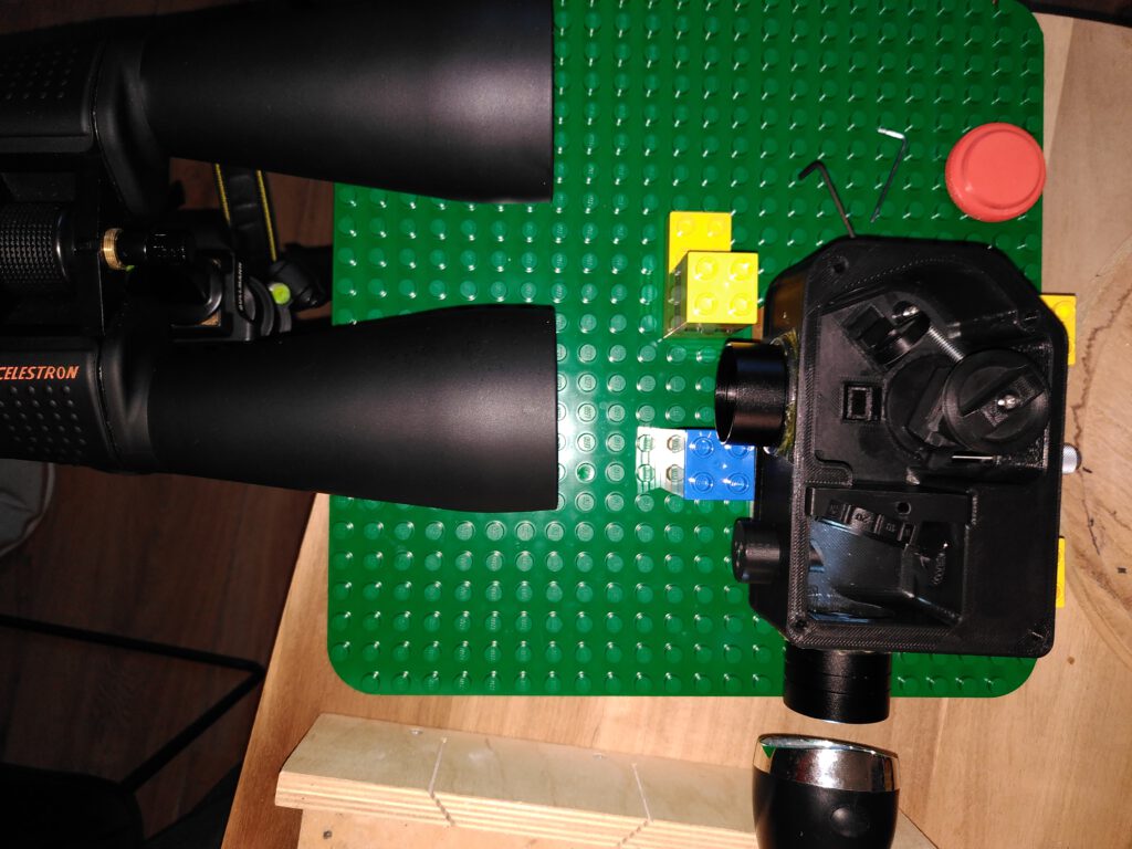
First make sure that the binocular (or scope) is focussed on infinity. You can do this by focussing it on something far away or on a star.
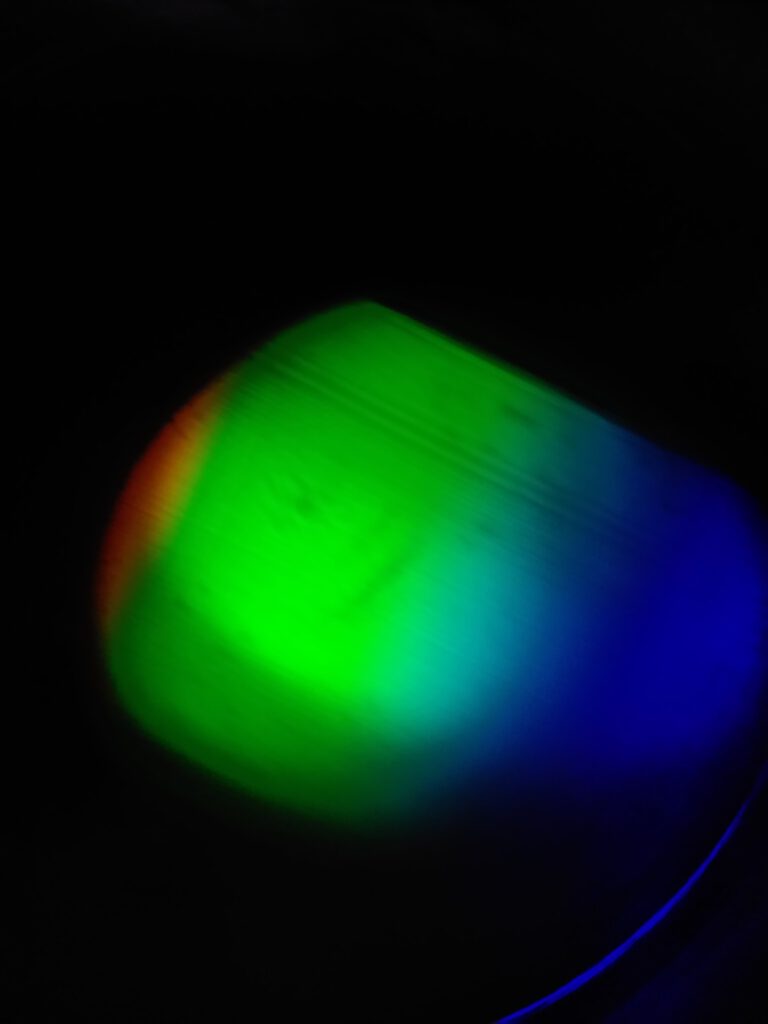
The purpose of the collimator lens is to make the divergent beam that comes through the slit parellel. After that it hits the diffraction grating and goes out the main camera end. When the collimator lens is in the right place, the spectrum you see in the binocular of scope should be in focus. For a source such as a LED aim for sharp top and bottom edges (like the image below). If you have a fluorescent tube around the house, use that. The emission lines in the fluorescent tube are very convenient to focus on, make sure they are as narrow as possible, as narrower lines means better focus.
While you are focussing the collimator lens, you can also adjust the mirror in the spectroscopy module by adjusting the 3 hex bolts to get the spectral image in the center of view. I also tweaked the center bolt of the mirror to get the distance from the slit to the collimator lens right. This gives you an extra parameter to get the collimator lens within the range of motion of the philips screw at the bottom of the housing.
Focusing the main camera lens
The video below shows how to move the camera lens in and out. It has quite a large range of motion (about 10 mm). This makes it forgiving for the backfocus of the main camera to the housing.
To get the main camera in the right back focus, I tried the M42 spacers I had lying around to get the back focus within the range of motion of the camera lens focusser on the Lowspec. When you know the approximate amount of spacers you need, you can get a more permanent spacer, made of the least amount of elements.
When you have determined the needed backfocus, I recommend that you attach a rotator that fits your cameras backfocus. Without the rotator you will be very unlikely to get the orientation of the camera exactly square to the the spectral image that comes out of the Lowspec.
To get the main camera in focus after focussing the collimator lens, you can just point the telescope end to the window during daytime. When in focus this will give you a typical spectrum of the sun (reflected by the atmosphere) with a lot of clear absorption lines. When in focus this will give you the following image.
At night time you can also swith on a fluorescent light in the room when you have that. I did that in my shed where my scope is stored and got the following. When you intent to do spectroscopy at night, it is highly recommended that you do this focussing allready beforehand at daylight, usting a calibration lamp, or the day time sky. That way it is far easier and the focus will not shift noticably after that.
Alignment of the guide mirror.
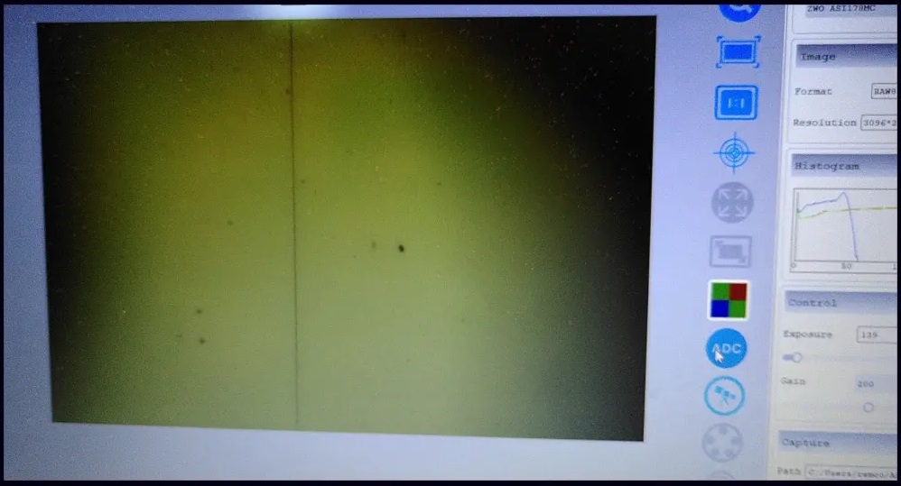
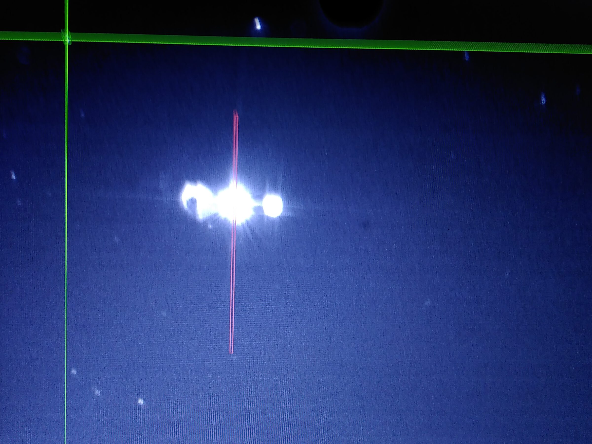
Aligning the guide mirror is easy with use of the 3 hex bolts and center bolt. These bolts adjust the pick of mirror in front of the slit plate. To do this, attach a guide camera to Lowspec and watch the guide image on a PC or laptop. And place a light source at the telescope end.
While adjusting the screws, makes sure that in the guide image the image of the slit is approximately in the middle of the image. At this point you can also adjust the rotation and the backfocus of the guide cam to get the slit image in focus and square in the image. It is strongly adviced to let the slit image run from top to bottom, square with the edge of the image (see below). This will make it easier to navigate while navigating to the right star in a star field.


Printing
I printed (or my brother printed 😉 ) the Lowspec with ASA fibre. It can also be printed in ABS, PET-G or probably in other materials. Anyway, avoid printing with PLA. PLA is partially transparant to near infrared. As CCD and CMOS sensor pick this up, a housing printed in PLA will give you weird gost images on the spectrum from near infrared light leaking though the housing. If you want you could print the lens holders that completely enclosed in the housing in PLA. But also avoid printing the partition between the the guide module and the spectroscopy module in PLA, for the same reason of light leaking through.
We printed all the housing parts in ASA, apart from the dust caps, those we printed in red PLA. For the printer we used my brotherd Prusia i3 with a heated bed. The largest part is the housing. This tends to warp a bit while printing and takes a long time (several hours). To reduce the warping, my brother altered the Thingiverse file and added a thin wall on the outside to creative a insulating cavity around the printed body. This reduces the draught around the cooling printed body and slow the cooling proces, reducing the warp.
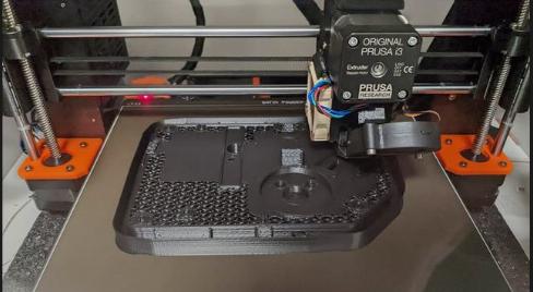
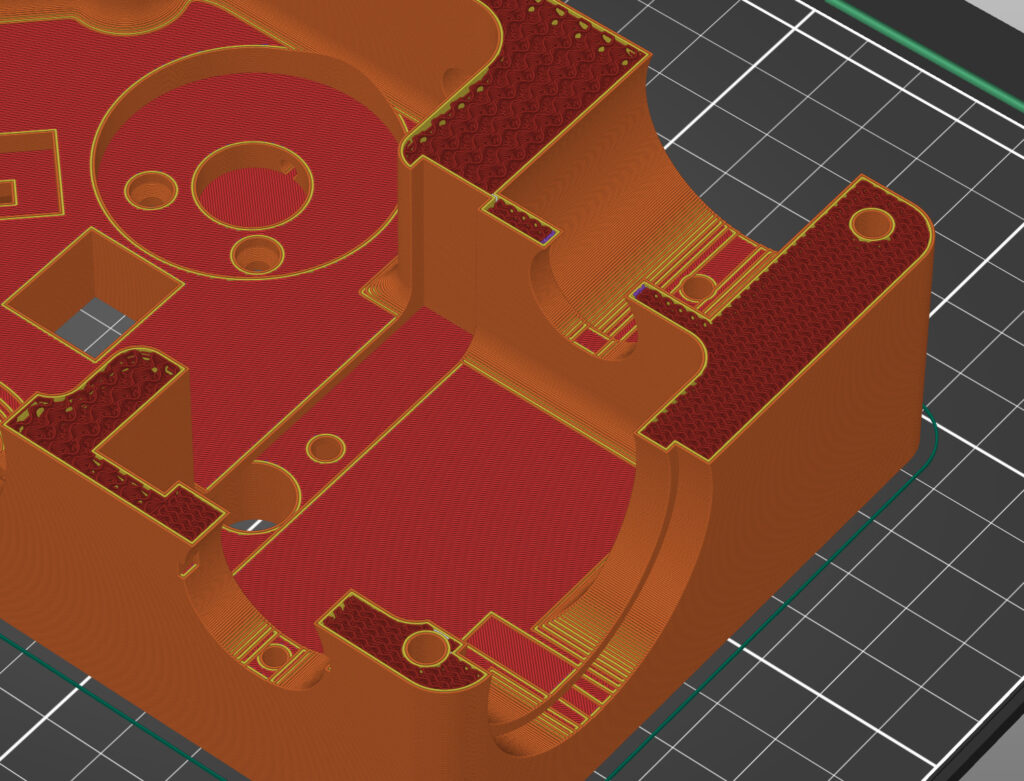
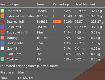
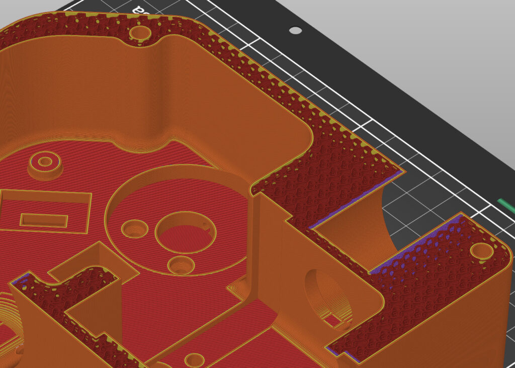
The main body was quite a long print of more than 1 day. For the infill we used the pattern shown below to save material. We used 3 perimeter layers as shown below. In total, a 1 kg spool of ASA was enough to print all the parts
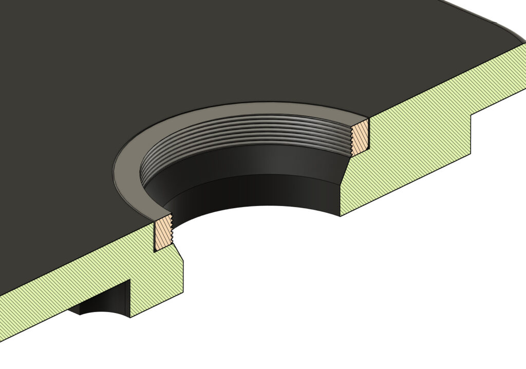
We altered the design on one point. The thread in the lid where the grating holder is screwed in. The lid is quite a large component to and could be affected by warp. In the first try that made it hard (or nearly impossible) to screw in the grating holder in the lid. We altered this by make the thread and the lid a separate component. Afterwards they are glue together with the 2-component epoxy glue that is also used to glue the printed M42 threads for the telescope end and the main camera in place.
Optical components
I have bought almost all my optical components for my initial setup (with 300 lines/mm grating) at Thorlabs. The Lowspec 3.0 building manual displays a clear overview of all the needed components. Make sure that you get the version of the lenses and mirror that are optimed for a wavelength around 500 nm. There are also those optimized for other wavelengths, and that will reduce the efficiency of your Lowspec.
As said I bought the slit plate at Jeulin
I have later purchased a additional diffration grating, with 1200 lines/mm for higher resolution. That I have purchased from Edmund Optics. For this you print an additional grating holder and a container to insert it into the body, and to store it while it is not used.
Mechanical components
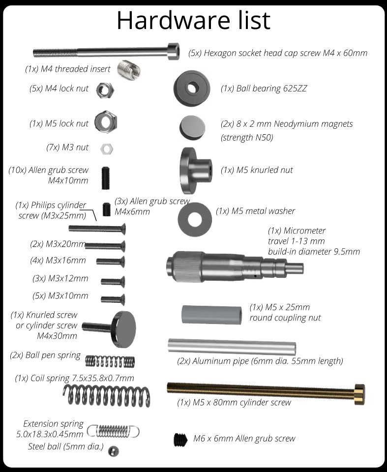
There are also a number of mechanical components needed. This overview is also in the Lowspec 3.0 building manual. I bought these at a hardware store in the Netherlands which sells them in single items (rvspaleis.nl) . For people in the USA and UK, note that all these components are metric sizes.
Theres is one mechanical component, the micrometer, which I also purchased form Thorlabs.
the aluminum pipe for the guide rails of the camera lens focussing mechanism I got from the local hardware store and cut them to the right lengt with a steel saw.
The springs and the 5mm steel ball I bought from amazon. I could find both only in large quantities so I have a lot of tiny ball bearings and springs left now 😉
Assembly
For the assembly I strictly followed the building manual Paul Gehrlach provided, and it was easier then I thought it would be. There are a few tools you will need to assemble the printed parts and the bolts and screws.:
- a tapping tool to tap M3 up to M6 thread into the printed parts, mainly for the grub screws.
- hexagonal keys for M3 up to M6.
- wrench for M5 nuts.
- small philips screwdriver
- metal saw to cut the aluminimum pipe to the right length
- 2 component epoxy glue. To glue some of the printed parts together.
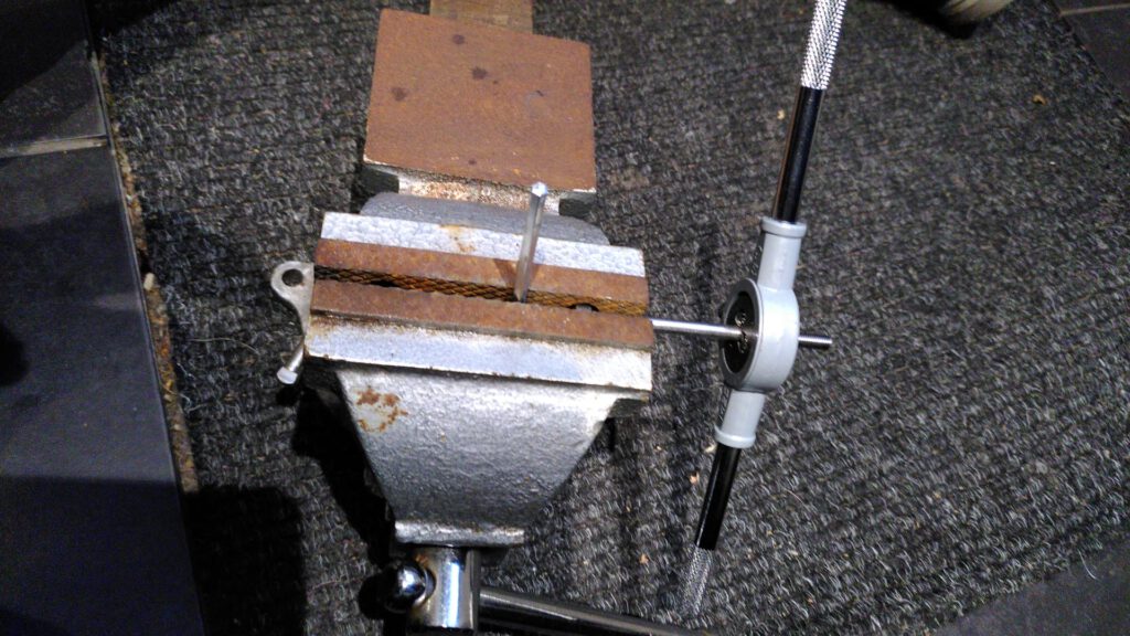
There was one part, the M5 x 80mm cylinder screw that I could not get the right version of. The version I could get my hands on had a thread that was to short. This screw is used to let the camera lens travel over. To make the thread longer I had to buy a tapping tool that can tap on to screws, (see above)
Connecting to the telescope
The Lowspec is connected to the telescope at the telescope end. My telescope is a 750mm F5 newton. This needs a coma corrector to get a flat field. I tried it at first without it as I thought coma would not be an issue as I thought the slit will be at the optical axis where there is little coma. The guide image below of the Orion nebula shows that there is significant coma, all pointing to the same side. This means the slit is not at the optical axis and that I had to add the corrector.
When you ad a corrector, the backfocus distance has to right. The coma corrector I used has a back focus distance of 75mm. Measure this distance from the flange of the corrector op to the center of the slit plate, as the focal plane of the telescope should be exactly at the slit. I had this GPU 1,1x coma corrector as an extra to my normal coma corrector with which I do imaging, so I could fix it more permanently to the Lowspec. I fixed the perimeter of the corrector and the spacers with duct tape to prevent them from turning loose while the whole weight is hanging to one side on the telescope.
If you have only one corrector to use, make sure that you can create a well fixed connections which does not come loose easily. Test this by connecting it to the telescope and slewing it both to the east and the west and see if it does not turn it self loose under gravity.
Wavelength calibration
To calibrate the wavelength of the spectral image, you will need a light source which has known spectral features. For low resolution spectroscopy, such as with the Star Analyzer filter, you can make use of a A0 type star (such as Vega) which has bright hydrogen balmer series features in it. However when you go to higher resolutions you would want to have a calibration lamp. At higher resolution the hydrogen features of a bright star are prone to doppler shifts which will throw the calibration of.
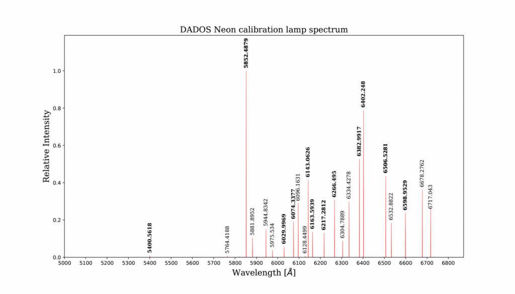
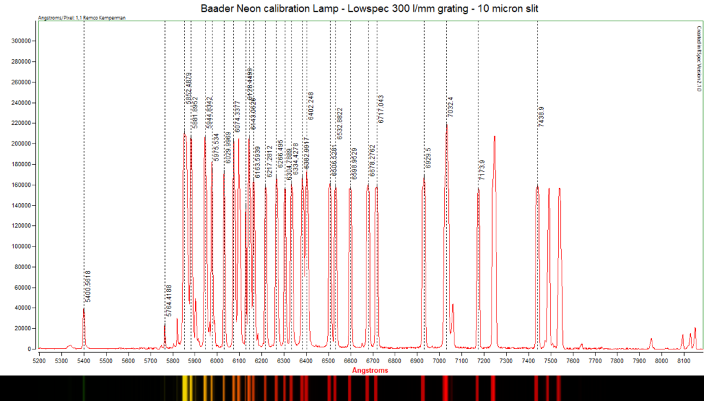
As a calibration source, I use a neon calibration lamp from Baader. This was meant for the Baader Dados spectrograph but I purchased it seperately, for 25 Euros. It comes with a documentation of all the bright emission lines in the lamp. These are mainly in the green, red and infrared part of the spectrum, from 5400 to 7500 Angstrom.
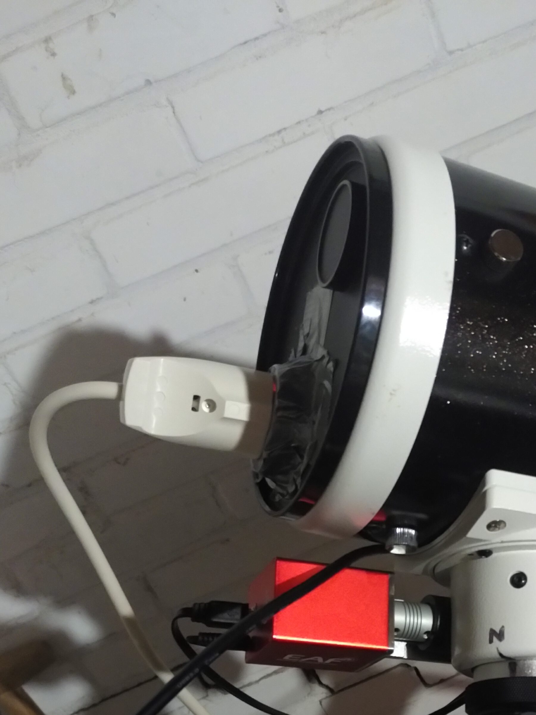
To use the lamp during acquisition, the whole setup up needs to be in the same position as it is when it points to the target. To fix this I taped the Baader lamp into the dustcap of the telescope. When I have found my target (star or nebula) I place the dust cap with Neon lamp on the telescope and take 3x 60 second images and stack those later. That image is used later for wavelength calibration.
When you slew to a different target, you will need to repeat this process again, as the spectrum will drift over the sensor due to flexture, at least in my case.
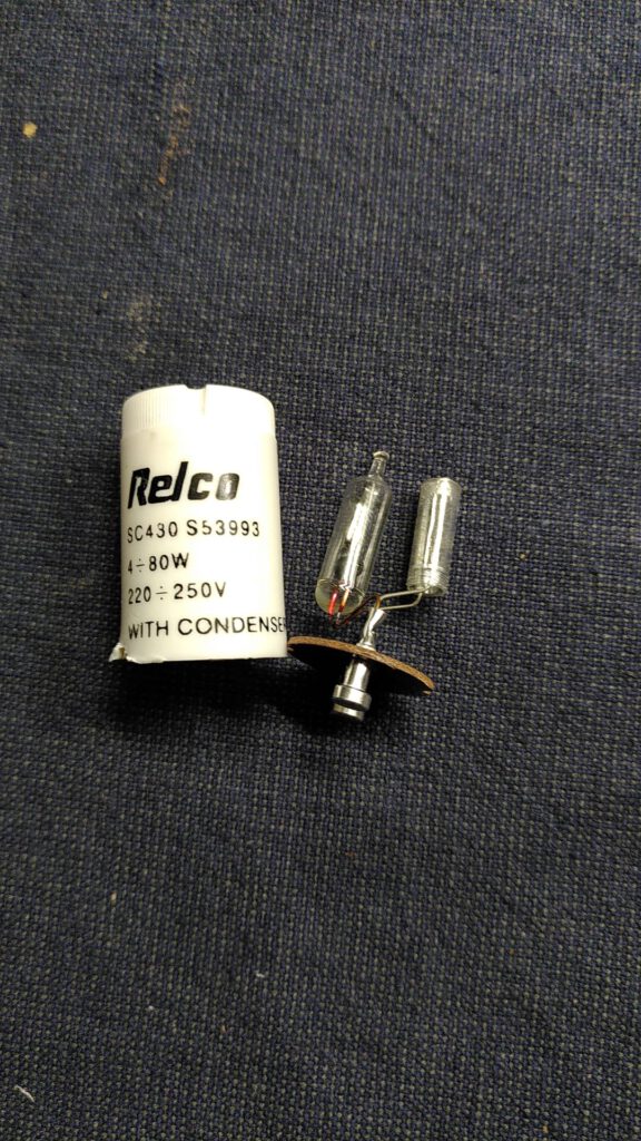
Improved wavelength calibration lamp (with Relco SC430 starter)
As the baader neon lamp misses spectral lines in the blue end (below 5400 angstrom), the blue part is missing. For that I still have to add some features from a bright A0 star (such as Vega) to fill in the gaps. This is not ideal. There are a number of people who have built there own spectral calibration source based on a Relco SC430 starter. In there is a Neon/Argon lamp which also has loads of lines in the blue part (from Argon).
I allready have a number of these Relco starters, but I need to build it into a calibration lamp and fit it somewhere in my system.
A few examples of people succesfully making a calibration lamp based on this light source are these:
- Relco SC430 lamp in a 3D printed housing, fitted at the front in a flip mirror https://stargazerslounge.com/topic/371311-calibration-module-with-relco-480-lamp-for-lowspec-spectrograph/
- Relco SC430 lamp built into the lid of the Lowspec 3.0 https://groups.io/g/astronomicalspectroscopy/topic/lowspec_3_0_comments/80976847?p=,,,20,0,0,0::recentpostdate%2Fsticky,,,20,2,0,80976847
Another consideration could be to purchase the calibration module of the Alpy600 from Shelyak. This module cost just under 900 Euro (in the EU incl. VAT) and is based on the same Neon-Argon lamp. Next to that it also contains a tungsten lamp for taking flats. If you are considering buying an Alpy or a UVEX spectrograph from Shelyak later; this calibration module fits on both of those Shelyak spectrographs.
Taking flats
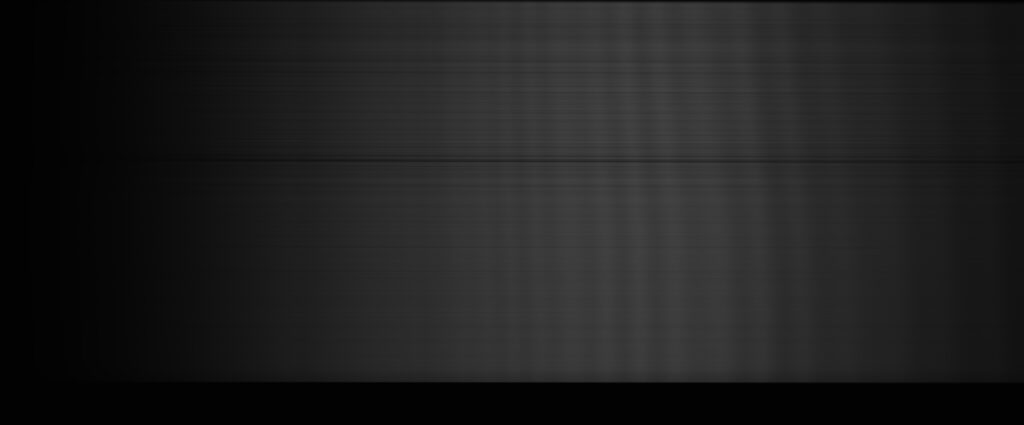
To create well corrected spectra you also need to do flat field calibration. This can not be done with day light, as the day time sky contains spectral features of the sun. This needs to be done with a incandescant lamp. For the time being I am using a halogen lamp is normally used for home construction. This is sufficiently hot to get a good cover in the visual spectrum.
An image of such a halogen lamp looks like this. Here you can see that response over the sensor and per wavelength is not uniform. The bumps on the far right (red side) are due to the angle with which the light hits the sensor. This effect can be calibrated out by flat calibration.
As said above, I still need to built a calibration module based on a Relco SC430 starter lamp. In this module I will probably also integrate a small tungsten incandescent lamp to take flats.
Downsides of Lowspec 3.0 (image drift)
I have found one downside with the Lowspec 3.0. At long exposures, typically multiple 6 minute exposures for faint targets, the spectrum tends to drift over the sensor due to flexture in the spectroscope. At bright targets that need exposures of a few minutes, this is not an issue.
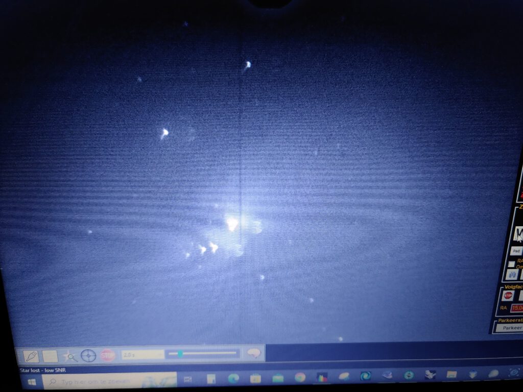
The animation below shows the raw, unstacked exposures of the star HD 226868 orbiting Cygnus X-1 black hole. For this target I exposed 25 times 6 minutes. At those lengths the drift over the sensor is obvious and you can’t stack the images without first aligning them.
I have found a way to manually align the frames, based on the bright light pollution lines. I do this in PixInsight by using the dynamic crop tool and blink back and forth between frames to alter the center of the image. This is a tedious job, but it works. The image below is the result of aligning and stacking the animated frames above. If someone knows of a software that can do registration which does this automatically, pleas let me know 😉
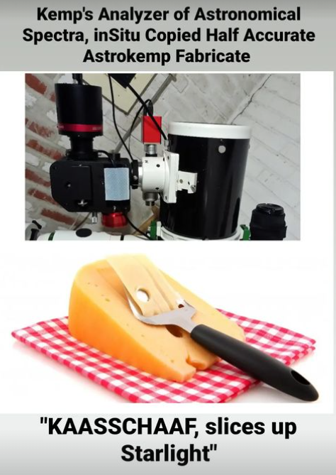
KAASSCHAAF
As any proper astronomical instrument, my spectroscope of course needed a cheesie acronym. As a enthousiast of cheese, and avid user of the typical Dutch kaasschaaf (cheese slicer) I took this as an acronym ;). KAASSCHAAF is now ready to slice up starlight into it’s constituent wavelengths!
Lowspec as a visual tool
The lowspec can also be used as a visual spectrograph. In this way it is fun to point the telescope end at the daytime sky, or at any kind of lamp or light source that can be found around the house to see the spectrum of it.
In my case I use a 28mm 2″ eyepiece for visual use. Allready with the 300 lines/mm grating you can see all the Fraunhofer spectral lines in the sun when you point it at the daytime sky. If you point it at the gas furnace, you can see the distinct orange emission line of carbon when the stove flickers an orange flame between the normally blue flame. If the light level is too low for your eye, you can easily increase it by turning the slit plate for a wider slit (at the loss of resolution).
Resources for building the Lowspec, and other 3D printed spectoscopy projects.
Beside me there are a bunch of people who have allready built the Lowspec, both the 2.0 or 3.0 version. The links below show examples of people building and using the Lowspec. A number of those I also used to get to grips with the building proces.
Astrojolo is someone who built the Lowspec 2.0.
https://astrojolo.com/more-than-pictures/lowspec-amateur-spectroscope/
https://astrojolo.com/spectra/
Majadahonda also built a Lowspec 2.0. And beside that upgraded it with motorized focussing and motorized a grating angle for selecting the wavelenth range. He mainly uses it in high resolution configuration.
https://www.observatorio-majadahonda.com/spectrograph-lowspec-3d
David Kruse made 2 videos about the building proces of the Lowspec 2.0 version.
Video 1 is about the printing proces. Video 2 is about the assembly and aligment of optical parts.
https://www.youtube.com/playlist?list=PLnZ_rvnR35rdopw2GSKFo_VYyAG9P6jDB
troscopy workshop.
Sol’ex / Star’ex slit spectroscope
Christian Buil has also designed a 3D printable spectrograph, called the Sol’ex or Star’ex. The optical parts for this design are available through Shelyak. (see the link below)
https://www.shelyak.com/produit/solex-optical-kit/?lang=en
The Sol’ex is a heliospectograph whith which you can take images of the sun, using a high resolution spectroscope. The Star’ex is a extension on the Sol’ex. Here the Sol’ex is extended with a guiding module to make it usable on stars. Just as the Lowspec design, you can interchange the diffraction grating to alter the spectral resolution.
Dark Sky Geek made a video trilogy about the Star’ex. Video 3 also includes his workflow at night taking spectra. It is quite similar to my workflow, using multiple instances of NINA for; the main camera, the guide camera, the finder camera, controlling the mount, stellarium, and using PHD2 guiding for placing the star exactly on the slit and guiding to keep it there.
Video resources from AAVSO
This AAVSO ‘How to’ webinar below also has Tony Rodda tellig about a number of DIY spectrograph projects, including the Lowspec.
In 2021 the AAVSO has held a spectroscopy workshop. This is worthwile to watch if you want to get started in spectroscopy with a slit spectrograph.